
For quite some time now I’ve been running my Wanhao Di3 with the cover of the console/controller box removed so that the stone age Melzi controller board and its rat’s nest of cables is visible. I don’t recall exactly why I removed the cover in the first place. Maybe I was concerned with airflow around all of the cables that end up stuffed into the space around the fan. Or maybe I was trying to read something on the board. Whatever the reason, for once I ended up being thankful for having left a long-term mess on my desk.
I was just finishing up a print for a new X-axis limit switch bracket when I happened to look down at the Melzi board and spied something pretty disturbing. The insulation around the power supply’s common wire, where it disappeared into the terminal block on the board, had a decidedly melted and charred look about it. On closer inspection I discovered that even the terminal block was melted, and so much so that I couldn’t loosen the screw holding the wire in place without fear of twisting the block right off the board.
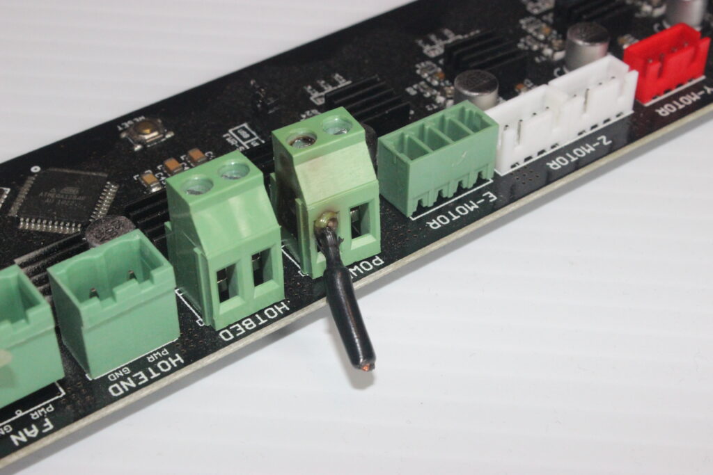
My head was suddenly spinning with memories of all those photos drifting around the Internet from early 3d printing enthusiasts whose printers had caught fire because of sub-par components and poorly designed controller boards. Suddenly a new, urgent and not entirely welcome task stepped to the front of my queue of projects. I had to upgrade my controller board.
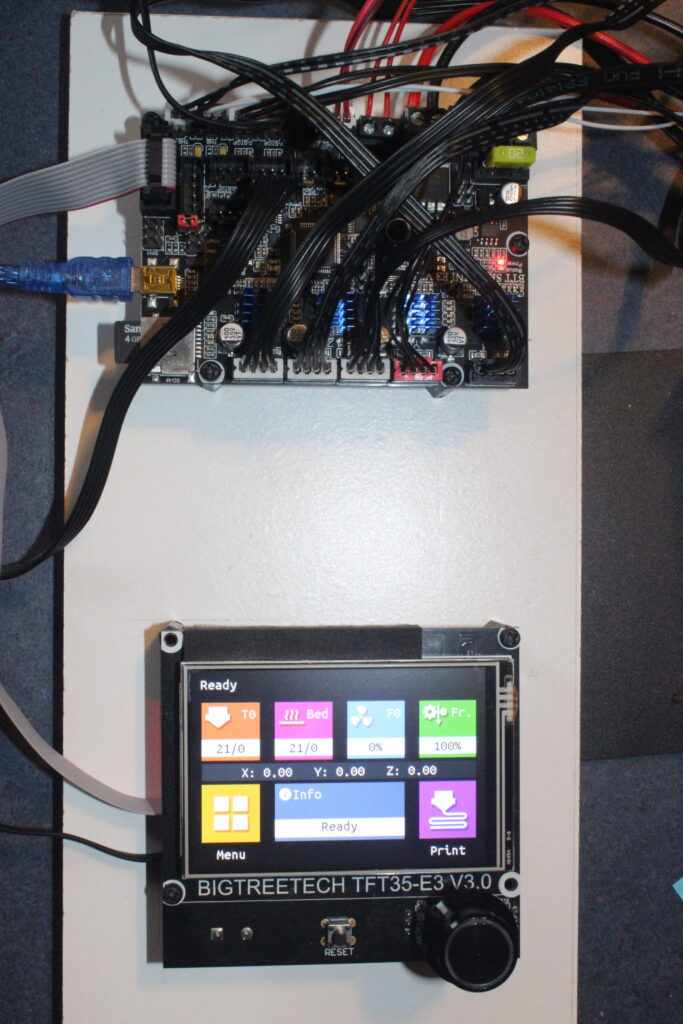
In January of 2021, I purchased on Amazon a Bigtreetech SKR E3 Mini V2.0 controller packaged with a TFT-35 E3 V3.0 display module. I had been wanting to upgrade to a modern 32 bit board for quite some time, hoping to improve G-code processing speed and have more RAM for Marlin features. I was also looking forward to modern stepper drivers that might run the steppers a little quieter. E3 Mini and TFT-35 had been sitting in a drawer for months; I didn’t even know if they worked. It was time to find out.
Wiring up the new board and display was straightforward, though I did have to change the connector for one of the fans as well as for the extruder stepper. Michael’s video, on his Teaching Tech channel, was an invaluable and detailed introduction to the board. I did spend more time than I wanted searching the internet to discover more details about the several jumpers on the board. The documentation at BTT’s github repo could have been better in this regard. This thread helped to explain some of the text in the BTT documentation. The table appearing in that thread is reproduced below.
| Jumper Label | Description |
|---|---|
| X-DIAG | If jumper set, sensorless homing will be used for X-AXIS (Note: cannot use external end stop if this jumper is set) |
| Y-DIAG | If jumper set, sensorless homing will be used for Y-AXIS (Note: cannot use external end stop if this jumper is set) |
| Z-DIAG | If jumper set, sensorless homing will be used for Z-AXIS (Note: cannot use external end stop if this jumper is set) |
| E0-DIAG | ???, not sure what E0-STOP is for, the original control board doesn’t have this |
| Power selection for BLtouch | If jumper set between pins +5V and PWR: The onboard +5V power supply will be used for BLtouch; If jumper set between pins PWR and VOUT need to use external BIGTREETECH DCDC5V V1.0 Module |
In the end, I didn’t change the settings of any jumpers on the board. But while we’re on the subject of jumpers, I also discovered that there is no jumper to prevent the board from being powered by another host plugged into its USB port. While bringing up and testing the board, I was connecting it via USB to a Raspberry Pi running OctoPrint. When the board was disconnected from mains power, it was still, to some degree, powered up through the Pi. This is apparently a common problem for Creality owners, the target upgrade market for the BTT SKR boards. There is more than a little chatter on the internet about how sending power to the board’s USB connection can fry board components in certain situations and I’m probably lucky to have not damaged the board before it was fully functional. My short-term fix for this problem was to place a piece of electrical tape over the 5V pin on the Pi’s end of the USB cable. The longer-term fix was the purchase of this USB power-blocker from Amazon.
The exact role of the TFT-35 display took a while for me to understand. While the Teaching Tech video referenced earlier does a good job of describing how to wire the display to the E3 Mini, it wasn’t clear if I should think of the display like a monitor being plugging into a PC or as a stand-alone controller, given that it is endowed with its own ARM-Cortex M3 CPU. This video from Daniel on the CrossLink channel explains how it is both. The TFT-35 E3 can be operated in one of two modes that can be switched between at run time. In the Marlin LCD 12864 simulation mode, it talks at a very low level to the E3 Mini and acts similar to an old-school dumb terminal; the E3 Mini tells the board exactly what pixels set or clear on the display, and reads input from the button/knob. In touch-screen mode, it talks to the E3 Mini over RS-232 using G-code and acts more like an independent controller similar to OctoPrint. Each mode has its advantages.
Unfortunately, the E3 Mini and the TFT-35 E3 don’t fit into the Wanhao’s console box where the old Melzi lived. Or maybe this mis-match is in fact fortunate since I never really liked that gigantic console box. To keep things somewhat organized until I have fabricated a proper case for both the E3 Mini and the TFT-35, I mounted them on standoffs screwed into a scrap piece of wood.
The software side of things took a little longer to sort out. Some time ago I built a customized version of Marlin 1.1.9 and installed that on the Melzi, but Marlin 2.0 no longer compiles with the Arduino IDE. The Marlin site has very good documentation on how to compile Marlin 2.X using VSCode and the platformio module. In no time at all I had a working build environment on Ubuntu and was building Marlin 2.1.1 images. I stumbled a bit before working out that I should set the platformio default_envs variable to STM32F103RC_btt rather than STM32F103RC_btt_USB. The latter builds an image that makes an SD card inserted in the board’s SD card slot look like an external USB drive to the Raspberry Pi running OctoPrint. While this might be necessary for allowing the Pi to update the board’s firmware, it seemed an unwanted complication for the initial bring-up of the board.
From there it was a matter of modifying Configure.h and Configure_Adv.h to match the details of the E3 Mini and Wanhao Di3.
For me, by far the most difficult changes to Configure.h and Configure_adv.h were in setting the stepper current parameters for the TMC stepper drivers used by the E3 Mini. I’m thankful to this blog post at “It’s All Lost” for giving me a place to start my research and compare my numbers.
The max current for each A4988 driver on the Melzi is set using a voltmeter and by tuning a small potentiometer soldered onto the board. On the other hand, the max current for the TMC drivers is set in software; specifically in the case of Marlin, in Configuration_adv.h. I was confused for quite some time in trying to translate the method for computing VRef for the A4988 to the value of the RMS current to place in Configuration_adv.h. In the end it was far easier than I was trying to make it be.
It took me a while to understand that the technical specs for stepper motors most often express max current as RMS current. And while nobody, as far as I’ve been able to tell, has been able to find spec sheets for the Moons’ Industries steppers shipped on the Wanhao Di3 v2.1, years ago Jim Shank was able to decode the model numbers and documented it here.
The model numbers for the steppers on my printer are the following.
| Axis | Stepper Make and Model |
|---|---|
| X, Y, E | Moons C17HD40102-01N |
| Z | Moons C17HD6039-06N |
The three digits just before the dash are the stepper max winding current in “centi-amperes”. So for the X, Y and E steppers, the max RMS current they can handle is 1.02A and for the Z stepper it is 0.39A. I configured X and Y to be 80% of the max RMS current; 0.8 * 1020mA = 816mA. I configured E to be 90%, 918mA. I configured Z to be 90%, 702mA, but had to remember to double this figure since the Wanhao Di3 uses two Z-axis steppers and the E3 Mini’s single Z-axis driver must deliver enough current to drive both of them. To be clear, the E3 Mini provides two ports for Z-axis steppers, controlled with a single driver. And don’t make the mistake of telling Marlin that you have two Z-axis steppers; from Marlin’s point of view, it has to control only one Z stepper. In practical terms, this means changing the settings protected by “#if AXIS_IS_TMC(Z)...#endif” and ignoring those protected by “#if AXIS_IS_TMC(Z*)...#endif” settings.
As for the current on E being 90% rather than 80% of max RMS current, that was the result of experimenting to eliminate artifacts related to uneven extrusion. In the end, I don’t think the uneven extrusion was related to the stepper current and I could now probably safely dial that back down to 80%.
All told, it took several days to arrive at the final values for the stepper currents. Initially my parts were coming out millimeters shorter than their designed dimensions and were sporting other strange artifacts. After a good deal of head-scratching, I realized that I had configured the Z-axis stepper current far too low. In retrospect those steppers must have been missing a lot of steps.
The time spent researching software and hardware details was well worth it in the end and the remaining steps to bring up the board were very straightforward. Flashing the E3 Mini is easy; just copy the .pio/build/STM32F103RC_btt/firmware.bin compiled with VSCode onto the mini SD card and boot the board with the card inserted. When I connected the Pi to the board’s USB port, I was relieved to see OctoPrint recognize the board with no difficulties. I then used the OctoPrint terminal to send G-code to read the state of the endstops as well as move the X, Y, Z and E axes a few millimeters. This was a good strategy (compared to jumping straight into a print) as it turned out that I had incorrectly configured the direction of every stepper. It took only a couple of iterations to build a version of the firmware that had all of the motors moving the direction they were asked to, and for endstops to correctly report their state.
As I started my first test print, I was absolutely astonished at how quiet the steppers were. By far the noisiest components are now the fans, especially the PSU fan.
I did have some initial hiccups where Marlin’s thermal runaway detection would be tripped in certain situations when the part cooling fan would come on. In these cases, the hotend temperature would drop several degrees C and not recover in time. In trying to address this problem, I discovered that Marlin 2.X includes a new, experimental algorithm for regulating the hotend temperature called Model Predictive Temperature Control. This model is interesting in that, unlike PID control, it models heat transfer in the physical system consisting of the heater cartridge, heater block, fan, and filament. It also takes into account the hotend’s distance from the print bed. This last bit was of particular interest to me since my leading theory was that my DiiiCooler fan shroud was cooling my hotend too much when sitting over a large, flat surface. That surface trapped part-cooling air around the nozzle and my stock, 12V heater cartridge just isn’t up to the task of heating up fast enough for the default Marlin settings.
I swapped MPCTEMP for PIDTEMP in Configuration.h, built and installed a new Marlin image, and ran the MPC calibration routine. My next several prints completed without triggering the thermal runaway condition and the temperature graph displayed in OctoPrint was very steady for the entire duration of the print. I did trigger thermal runaway conditions a couple of times after that change, but that’s a topic for another post. I’ve been running with the new boards for a while now, still mounted on that scrap piece of wood, looking a bit like a sad little robot in the middle of open heart surgery. I’ve had no trouble with them and am very satisfied. Overall, it wasn’t that much effort to bring up the boards. Between the OctPrint page and the TFT-35’s touch-screen mode, I never feel the need to use the LCD 12864 simulation mode. I like that the E3 Mini is 32-bit and has more RAM for Marlin features and I absolutely love how quietly the steppers run now. And while there are no guarantees regarding components and fire-safety, I’m fairly confident that compared to the Melzi, the E3 Mini, coupled with Marlin’s thermal runaway detection features, have significantly reduced my chances of burning down the house.
You can grab my Configuration.h and Configuration_adv.h from github with the following.
git clone -b 2.1.1-skr-e3-mini-v2 --single-branch https://github.com/nodcl/Marlin.git