
Introduction
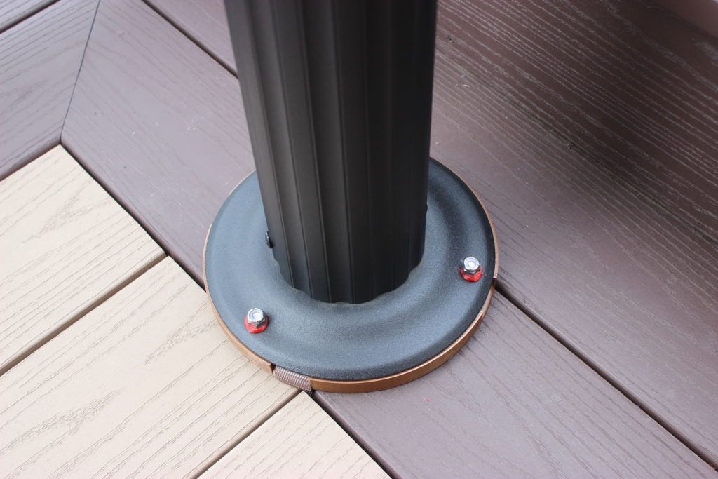
We recently purchased a ‘gazebo kit’ and installed it on the raised deck attached to the back of our house.
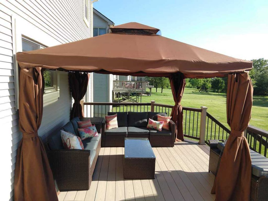
The structural components, e.g., columns, roof supports, etc, are made of extruded aluminum, and as can be seen from the photo, it has a cloth, tent-like roof. So far we’re fairly satisfied with it but there remains the problem of how to properly fasten it to the deck so that it doesn’t fly away in the heavy winds. Our deck faces due west and it’s not uncommon for us to get storms with really strong winds.
The base of each gazebo column is a disc of thin aluminum sheet pressed into an upside down bowl shape with three equispaced holes drilled around the perimeter.
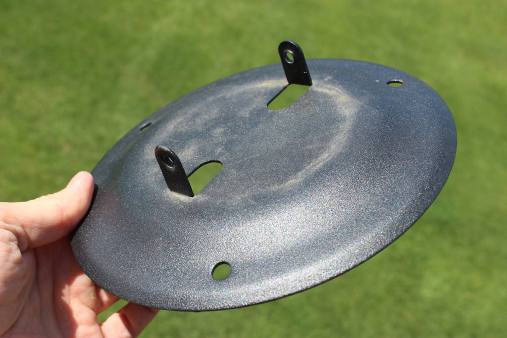
The manufacturer’s preferred method for securing the columns is to drive screws through these holes into whatever they’re sitting on. In our case, this would be into new, expensive Azek deck boards. I just couldn’t bring myself to do that.
In this post I’ll describe my alternative solution as well and the travails that accompanied the fabrication process.
The Tie-Down Puck
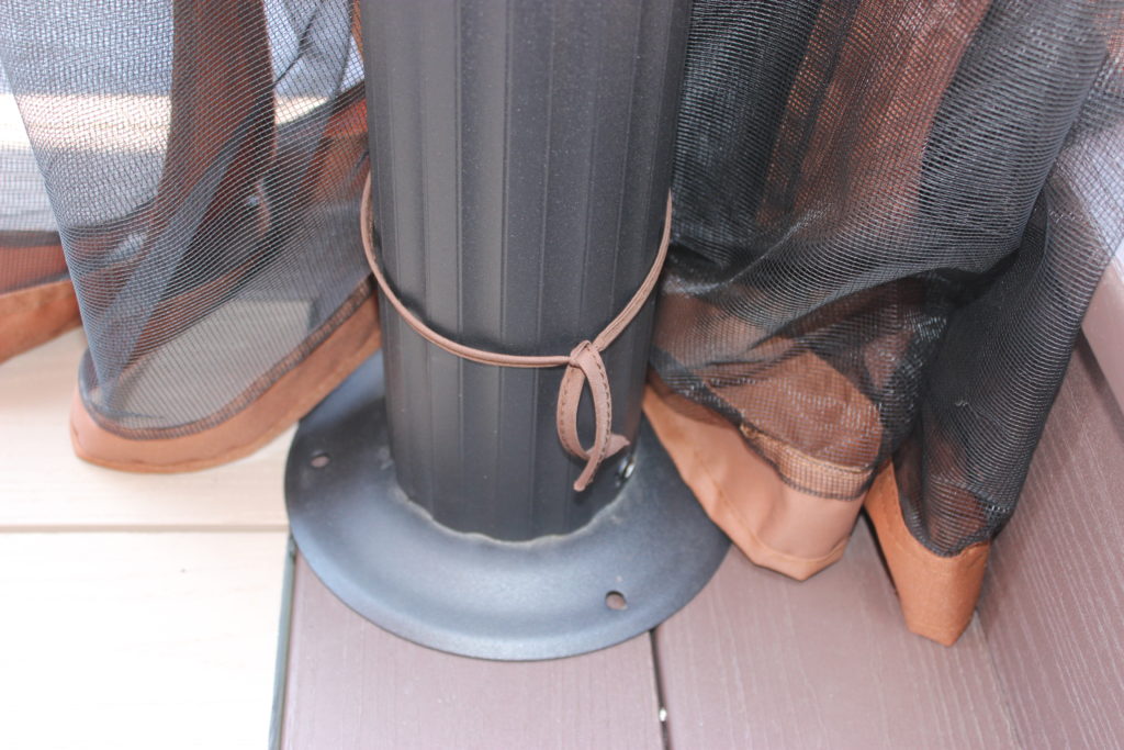
After thinkingfor a while about the problem, I came up with the idea of making a disk that would attach to the bottom of each column, and fastening that disk to the deck using a ratchet strap that passes through the space between adjacent boards and wraps around a deck joist. Ideally a strap will exit the interface between the column base and the puck at a right angle to the boards on which it sits so as to enter cleanly, and without twisting, into the space between boards. In order to make this more likely, the puck should be adjustable on the column base via a rotation over several degrees.
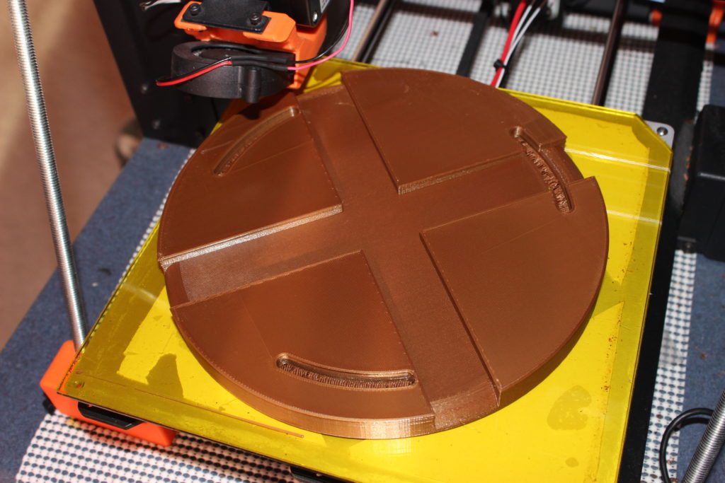
Below is view of the top of the first puck design that I actually fabricated.
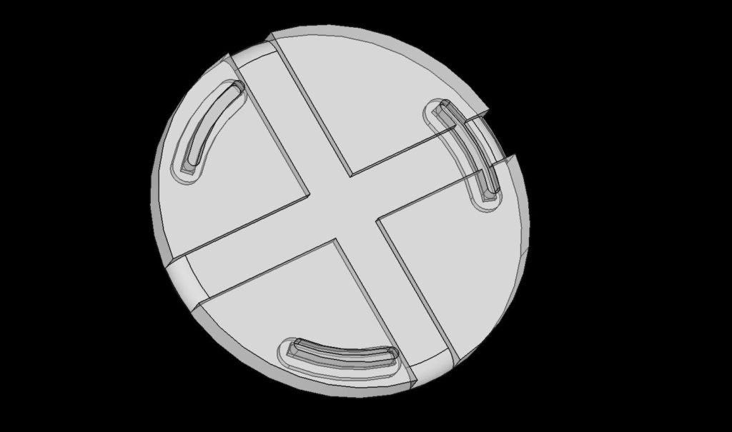
Design Features
The puck has two channels, intersecting in the middle at 90°, in which to pass a ratchet strap. Equally spaced around the perimeter of the puck are three slots through which carriage bolts will pass from the bottom. Grooves on the bottom of the puck track with each slot to allow for recessing the head of each carriage bolt so that the puck sits directly on the deck boards, and the weight of the column is distributed across the entire surface of the puck base rather than having it sit on the carriage bolt heads. The bolt slots, in combination with the two channels, allow the puck to rotate in order to have the ratchet strap enter the space between deck boards at an angle that, hopefully, is close to 90°.
The Modeling Process
As I always do, I modeled everything in this project using FreeCAD (in this case, version 0.19) on Linux. I first modeled the curve of the column base’s profile, a cross section of the upside down “bowl”, by using a metal profile gauge. I traced the profile from the gauge onto graph paper to get a series of measurements from the “ground” to the topmost surface of the base, transferred these measurements to a FreeCAD sketch, and fit them using a Bezier curve. I gave the curve the same thickness as the column base and rotated it around the Z-axis to create the “bowl”. Three properly positioned bolt holes around the perimeter finished this model.
Per my normal practice, I listed important dimensions for the column base in a FreeCAD spreadsheet object so that they could be easily found and referenced by the puck model. I did the same with the carriage bolts. I didn’t find a model of them online so I made a quick model with the dimensions labeled in what appears to be an industry-standard way, and stored them in another FreeCAD spreadsheet.
Modeling the puck was pretty straightforward, even though it did take several iterations for me to arrive at a modeling strategy that I was satisfied with. During this project I switched away from what had been my normal practice of attaching datum planes to surfaces and then creating sketches for features attached to the datum planes. During recent projects I’ve had the growing sense that this wasn’t the best way to model, despite having picked up that habit from advice in some FreeCAD forum. I kept running into situations where changes to some sketch early in the model dependency tree would break the model in hard-to-fix ways. During this project I instead made less use of datum planes and greater use of the global coordinate system. When it comes to CAD, I am self-taught. I’m sure professional CAD modelers would be horrified by my practices.
Designing for 3D Printing
I knew that I would want to print the pucks in the same orientation that they would be used – with the surface that sits on the deck being the first layer printed. This immediately presents a challenge for printing the bolt slots. A vertical cross section of the slot and groove shows that they have three widths. The grove at the bottom that accommodates the carriage bolt head is the widest. The slot sitting atop the groove narrows to the width of the square block that sits between the carriage bolt shaft and the head. Finally, the slot narrows again to the diameter of the bolt shaft. This progressive narrowing of the shaft from the ground up means that there are two 90° overhangs which, as we know, won’t print without some help.
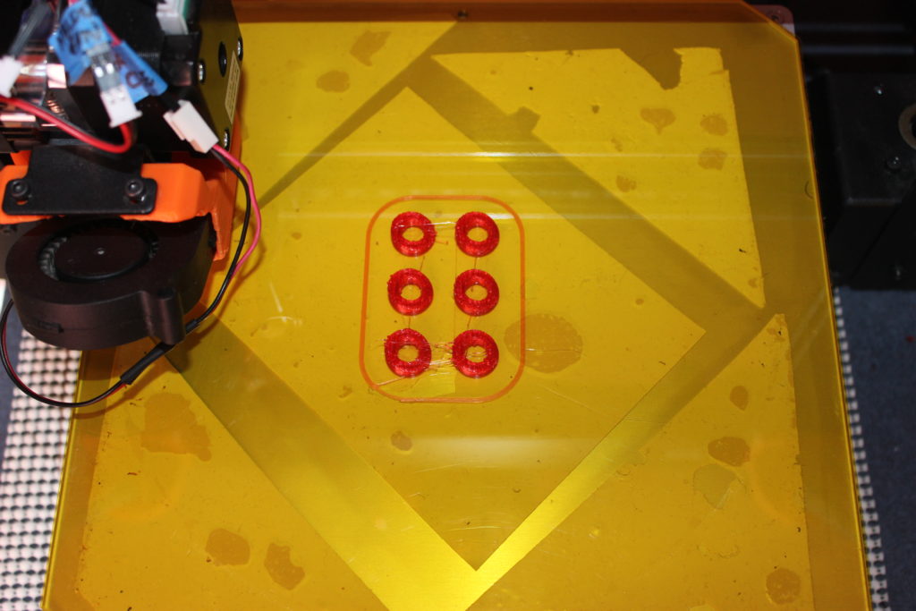
When preparing to print objects that take multiple hours to print, I will import the model into Meshmixer and use the Plane Cut tool to trim down the model and isolate a section to print by itself. I do this to verify that features are both dimensioned correctly (e.g. hole diameters), and will print correctly (e.g. angles for overhangs are not too aggressive). It’s better to verify these things with a print that completes in under an hour than it is to wait 14 hours for the entire part to print only to discover after 14 hours of print time (and a substantial amount of wasted filament) that the holes are too small.
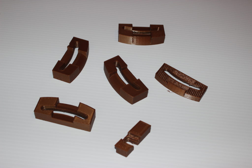
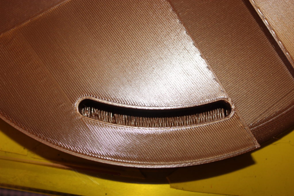
I followed that strategy for this project as well, wanting to verify that the slots had the proper dimensions and that the carriage bolt, once inserted into the slot, wouldn’t turn in place while locking it down with a nut. When slicing the “excised” portion of the model, I made Prusa Slicer auto generate support material and then printed the portion. Of course several of the dimensions of the slot profile weren’t quite right and I adjusted them. I iterated on this a couple of times, each time thinking about what a hassle it was to remove the support material and how ugly, and more importantly, how rough, the resulting part surface was. This roughness would make it harder for the bolt head to slide in its groove. And then I remembered the ‘design-for-3d-printing’ trick of designing into the model a ‘shelf’, the thickness of a single print layer, across a hole. The shelf is printed as a bridge feature and provides a good base for a smaller diameter hole to be printed on top of it. This shelf is simply cut out with an exacto knife after the print has completed and is much less work than removing support material and also results in a much cleaner surface.
I modified the CAD model to include two such shelves in the slot, excised the slot region using Meshmixer, and again sliced the excised region, this time without support. The result was all that I’d hoped for; a much better surface finish with far less post-print processing effort.
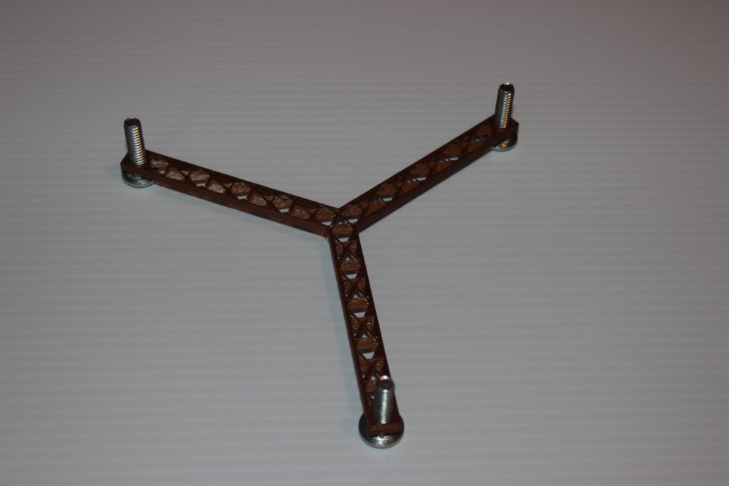
The next thing to verify was that the slots were placed at the correct distance from the puck’s center so that they would match the holes in the gazebo column base. If their placement was off by even a small amount, then the bolts would bind in the slots as they entered the holes in the column base. To verify the slot placement, I went back to FreeCAD and quickly designed a Y-shaped part with holes at the end of the “branches” of the Y that were at the same distance from the center as the slots were on the puck. This part, which didn’t even need solid top or bottom surfaces, printed quickly and showed me that the slot placement was not quite right. I updated my model of the column base, repositioning the holes slightly, and the changes cascaded into the slot placement on my Y-shaped calibration part, as well as into the puck. It required a couple of iterations to arrive at an acceptable placement.
Feeling like I’d overcome the challenges of the slot design and had reasonable confidence in slot dimensions and placement, I moved on to preparing to print the entire puck. This was to be the largest part that I’d ever printed and I would use PETG rather than say, PLA, because I’ve read that PETG is more resistant to sun and water exposure. I have good luck printing PETG on glass covered with kapton tape and I recently changed the glass in order to give myself just a little more print area, repurposing the glass bed from a scrapped printer/scanner. (That project deserves its own blog post.) I sliced the full puck at my standard process settings, a layer height of 0.1 mm and a 40% infill of a hexagonal pattern.
The estimated print time was 3 days, 12 hours and 13 minutes.
Clearly something had to change.
The most obvious setting to tweak in order to reduce the print time was the layer height. Given that, once installed, this part would hardly be seen and that there wasn’t a lot of complicated surface detail to render, increasing the layer height to 0.3 seemed reasonable. This change reduced the estimated print time to 1 day 10 hours and 12 minutes. Not bad, but could I do better? Infill was the next obvious thing to change. I was wondering if a different infill pattern might be appropriate for this project given that all of the forces on the puck would be compressive and spread around its diameter. This sent me off on a bit of an investigation of infill patterns and a revisiting of Stefan’s analysis that he published on his CNC Kitchen YouTube channel. A couple of years ago, when I was far less knowledgeable about 3D printing, similar research had left me with the impression that a honeycomb pattern was the strongest and therefore the best infill pattern to use. After reviewing Stefan’s analysis I understood selecting an infill pattern wasn’t always so straightforward. For this project I decided that a triangle infill pattern would be strong enough and because it requires fewer print head direction changes, the part would print faster. Changing from hexagonal to triangular infill reduced my print time to 18 hours and 14 minutes. Changing the infill percentage from 40% to 30% reduced that further to 17 hours and 11 minutes. My preference would have been to use Stefan’s special type of gradient infill but I decided that a 17 hour print time was acceptable and that it was time to move on.
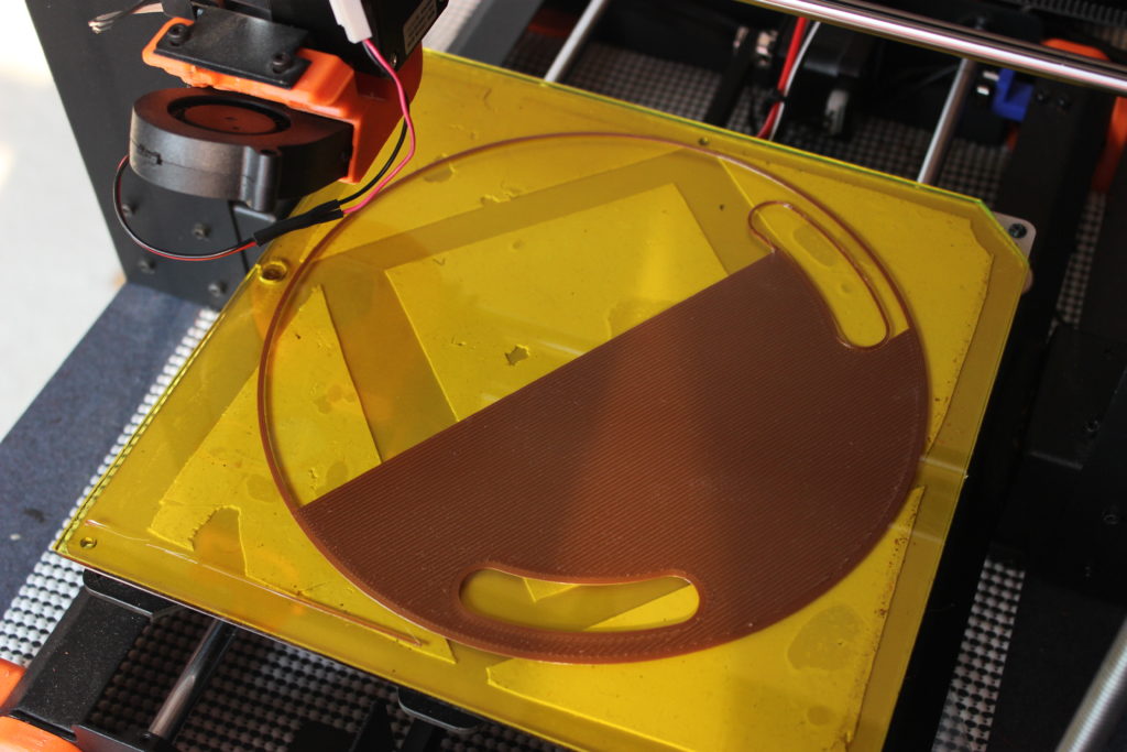
It was finally time to attempt printing the full part. The puck barely fits on the print bed and only if it’s printed without a skirt. For such a large object, with such a large area in contact with the print bed, I guessed that there wouldn’t be any problem with bed adhesion. I started the print and waited to verify that the first layer was printing ok. It was very satisfying to see a good first layer being put down across such a large portion of the print bed. I wandered away to let the printer print.
I checked on the printer after about five hours and right away I noticed a couple of problems. First, it seemed like the dimensions of the slots were off. I had made a change to their dimensions just before starting the print and a quick double-check confirmed that I’d messed that up. Secondly, the bridging angle for the “shelves” in the slots looked good for one slot, but not for the other two. I wanted the bridged filament to take the shortest path across the slot opening and for two of the slots the slicer was drawing the filament more along the slot’s “long direction” and I was worried about the filament not bridging well over those distances. I went back to Prusa Slicer’s preview mode and saw that the same angle was being used for each slot. Furthermore, the slicer’s “bridging angle” setting changed the angle for all instances of bridging in the project!
After a bit of research I stumbled upon the concept of Slicer “modifiers”. I’m relatively new to Prusa Slicer, having only recently abandoned Simplify3D because it has fallen so far behind in features; S3D doesn’t have such a concept. I went back to the CAD model and designed three bean-shaped objects that were slightly larger than the space occupied by each slot and positioned them so as to fully surround and encompass each slot. I then imported these shapes into the slicer and customized each bean’s bridging angle so that bridge features would be printed across the narrow dimension of each slot. In retrospect, maybe it shouldn’t be the shortest distance. In my bridging calibration tests, the shortest bridge always printed the worst.
It was time for a second run at printing the full puck.
Welp, I got further this second time. Seven hours in, Marlin falsely triggered a thermal runaway condition and stopped the print. Seven hours. Damn. Even with proper PID temperature tuning, my heater block seems to be barely up to the task of printing at PETG temperatures at a reasonably fast speed. Being confident in the printer’s wiring and connections and taking my fate firmly into both hands, I built and flashed a new version of the firmware with thermal runaway detection disabled and started a third attempt.
Three was indeed the charm in this case. The puck came out functional, though not without its problems. At some point during printing it started to curl up from the bed on at least one side. The effect was like having the rim of a bowl shrink a bit so that the print head was trying to lay down filament on the previous layer that had shifted just a little bit towards the puck’s center. This left a noticeable ring around the outside perimeter of the puck but more importantly, changed the clearances for the bolt slots. After a fair amount of work with the exacto knife and some fine grit sandpaper, I was able to salvage the part.

New problems awaited me in the printing of the second puck. This time the puck stuck better to the bed, though not perfectly; it very clearly was starting to pull up just a bit on one side. The part came off the bed easily but that’s when the new, show-stopper problem was revealed. My glass bed, the one salvaged from my all-in-one printer scanner, had cracked. This project seemed to be wanting to turn into a Quest.
I ordered a new borosilicate glass bed from Amazon and it arrived a few days later. A few days after that I applied a sheet of kapton tape to one side and began printing puck number three of four. And this time the print failed at hour 10 of 17 by popping completely off the bed! (You want a Quest?! Game on!) Things seemed to be going just fine up until the point where the top layers of the channels for the tie-down straps were being laid down. Thinking back over my previous attempts at printing this large disk, I realized that every attempt at printing this part saw some sort of bed-adhesion problem. I hypothesized that the adhesion offered by the large surface area of the base of the puck was not quite up to the task once the warping forces of the cooling plastic of the top layers of the channels came into play.
It was time to go back to the drawing board. I went back to my copy of Functional Design for 3D Printing by Clifford Smyth and soon wished I’d paid more attention to the advice on designing for bed adhesion. I had been operating under the assumption that a large, flat, round surface would have no problems with adhesion. Clearly this is not true in all cases and it was time to modify the design to try to minimize the contractive forces that were causing the part to pop off of the print bed.
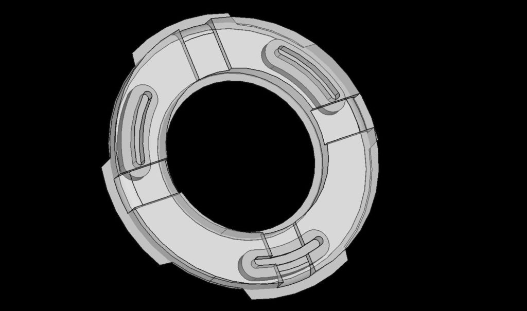
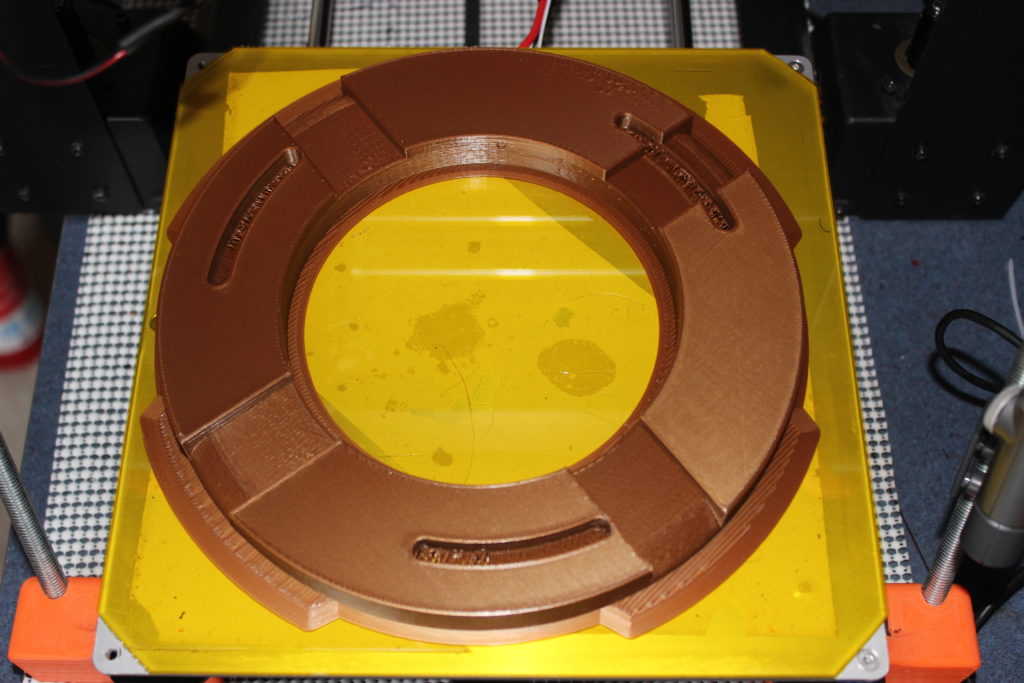
Once installed on the gazebo column, the primary forces on the puck are the compressive force, admittedly not very large, of the column bearing down on the perimeter of the puck and the force of the column lifting up on the puck, trying to bend it around the strap holding it to a deck joist, as a gust of wind tries to turn the whole gazebo into some sort of structured parachute. After thinking about what I could remove from the puck to reduce warping forces and yet preserve strength where it was needed, I decided to turn the puck into a ring. This reduces the length of the channel surfaces suspected of being the primary cause of the warping forces. Furthermore, not wanting to take any more chances with bed adhesion and because the part is still too big for it to be printed with an effective skirt, I designed in extra adhesion. This took the form of four single-layer (i.e. 0.3 mm thick) “tabs” that extend towards the corners of the build plate where I had plenty of space as well as along the inside edge of the ring. The new ring and adhesion are shown below.
This design printed very well. It uses a little more than half the plastic of the original design and prints in 11 hours rather than 17 and uses less than half the filament. I printed two of the new design; they adhered to the bed very well and also came off of the bed easily. An interesting side effect of the designed-in adhesion was that Prusa Slicer printed the tabs as part of the component’s first layer rather than printing them simply as a weak type of perimeter that follows the “real” perimeter of the component. This means that the ears were very solidly part of the component, rather than a weakly adhering skirt that is easily removed from the finished part. Of course this also means a little more work with a hobby knife is required to remove the ears, but given my earlier experiences with adhesion failures in the final hours of the print, I was more than willing to make that trade.
After printing a second ring, I was almost finished with the fabrication portion of this project. Given that the base of the column is an upside-down bowl, the nut going onto the bolt that attaches the ring to base won’t sit flat on the base. To address this, I designed a simple washer whose lower surface matches the contour of the base and whose upper surface is flat. I printed 12 of these using TPU, a flexible filament with which I’ve had a lot of success on other projects.
Installation and Assembly
To complete the BOM, I purchased stainless steel carriage bolts and lock nuts from my local hardware store and polyester straps with stainless steel buckles from www.strapworks.com. I chose polyester for the strap material based on guidance at the Strap Works website that showed it having the best UV resistance, abrasion resistance, water resistance and strength properties. Installation went fairly smoothly. The pucks and rings attached to the column bases easily and rotated easily enough that I could get an orientation that wasn’t too horrible for the straps as they went between the deck boards. In all but three corners the straps went easily through the spaces between the boards and there was a joist placed close enough to where the column sits to latch the straps around. The deck boards under the fourth column required a little gentle coaxing from a pry bar to allow for threading the strap between the boards, as well as the installation of a cross member between the joists for attachment.
Things I Learned
Infill geometry can make a big different in print time
Large bottom surface areas don’t necessarily imply reliable bed adhesion.
Designed-in adhesion can be stronger than a slicer-generated skirt due to the orientation of the lines laid down
When designing a custom shape to import into Prusa Slicer as a modifier mesh, design it in the same coordinate system as the part and export both the part and the modifier shape in amf format. This format preserves the part coordinates and eliminates the need to reposition the mesh shape from within the slicer.